Choosing the right method for defining the location of features on a part is vital for engineering, inspection, and manufacturing teams. Two approaches dominate this space: traditional coordinate dimensioning and Geometric Dimensioning and Tolerancing (GD&T) position control. Understanding the advantages and limitations of each approach leads to better part quality and more efficient production.
GD&T Position vs Coordinate Dimensions, Which is Better To Use?
Most engineers, designers, inspectors, and machinists are familiar with coordinate dimensioning and tolerancing for locating features of size. However, GD&T position control is becoming increasingly popular as a more reliable alternative. At first glance, GD&T might seem more complex, but a closer look reveals some clear advantages. This article compares coordinate dimensioning with GD&T position, explaining why many professionals are making the switch.
What is GD&T Position?
GD&T position uses a symbol—a feature control frame—to define the allowable location of a feature, such as a hole, relative to one or more datums. Instead of allowing the feature to drift within a rectangular area defined by coordinate tolerances, GD&T position defines a round (diametric) tolerance zone. This means that the axis of the feature must stay within a cylindrical area, which more closely matches the functional requirements of many assemblies, especially when dealing with round holes and fasteners.
The position tolerance is assigned via the feature control frame, and the values used are basic dimensions. This approach establishes true position, which can be checked by measuring deviation in both X and Y and calculating the total diametric deviation. The allowed deviation is not just a single two-dimensional measurement; multiple measurements may be taken down the entire depth of a hole to ensure the worst-case scenario is within the required tolerance.
Another key benefit of GD&T position is the use of datum feature references. This sets up a repeatable measurement datum reference frame that mimics the functional intent of the part. For example, if a part’s edge has some form error, using a datum ensures that the measurement reflects how the part will actually assemble, rather than relying on a two-point measurement that may unnecessarily reject good parts.
What is Coordinate Dimensions?
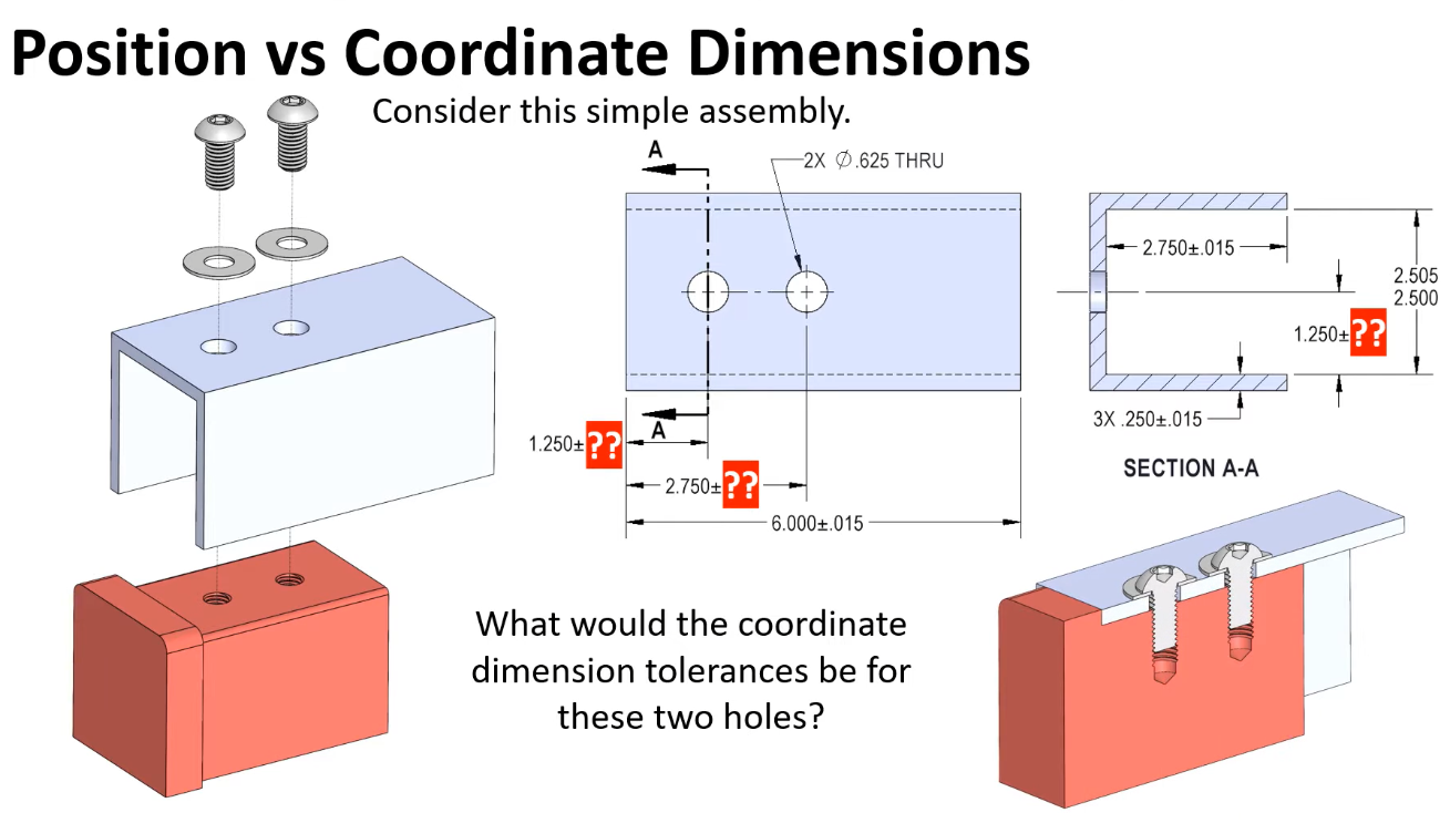
Coordinate dimensioning uses X and Y values with directly applied tolerances to define the location of features. In this method, the allowed drift for a hole or feature is defined as a rectangular tolerance zone. For example, if the tolerance is set at ±0.004 inches in both X and Y, the axis of the hole must stay within a rectangle with those boundaries.
However, this approach has a fundamental limitation. When the feature deviates by the maximum amount in both X and Y, it still passes inspection, but it could cause interference in assembly. To prevent this, the tolerances often need to be tightened. Using trigonometry, it can be shown that the maximum combined deviation allowed in both directions is less than the individual X or Y tolerance, resulting in a smaller rectangular area.
This stricter requirement can lead to good parts being rejected or bad parts passing inspection. For example, if a hole deviates by the full amount in X but not in Y, it still fits, but the inspection criteria might still reject it due to the tight tolerances. Coordinate dimensioning does not account for the combined effect of deviations in both directions, which can be problematic in practice.
The Problem with Coordinate Tolerancing
Coordinate tolerancing often forces a choice: either reject usable parts or accept those that shouldn’t fit. There’s no way to account for combined deviations in X and Y without also accepting combinations you don’t want. This highlights a key shortcoming of coordinate dimensioning.
How GD&T Position Tolerance Solves These Issues?
This challenge is exactly why GD&T position was developed. Fasteners, which are round, are better represented by round tolerance zones. With GD&T, a feature control frame can specify a diametric tolerance zone for a hole’s position, including only those locations that ensure functionality.
Calculating the area of a circular (GD&T) tolerance zone compared to the traditional rectangle shows a major difference: the circular zone provides about 57% more tolerance. This allows all viable hole locations while blocking those that would fail the assembly.
Converting Coordinate Tolerances to GD&T Position Tolerance
If you have a print with coordinate dimensioning and suspect extra tolerance is being excluded, you can convert directly to a GD&T position tolerance. To do this, calculate the equivalent diametric tolerance using the Pythagorean theorem:
- Find the hypotenuse using the X and Y deviations:
C = √(A² + B²), where A is the X deviation and B is the Y deviation. - Multiply the result by two for the total diametric deviation.
For example, with ±0.003 inches in X and Y, the total diametric deviation is 0.008 inches. Assign this value in the feature control frame and convert the tolerance dimensions to basic dimensions, establishing true position. This simple change grants the quality department 57% more tolerance to work with, without increasing the actual clearance.
Inspection and Verification
The same principle applies during inspection. Measure actual deviations in X and Y, use the Pythagorean theorem, and compare the calculated diametric deviation to the allowed value. If, for instance, a hole measures 0.003 inches away in X and 0.002 inches in Y, the total diametric deviation is 0.007 inches, which passes if the requirement is 0.008 inches.
It’s important to measure at multiple depths to find the worst-case scenario. For ease, reference charts are available to quickly convert coordinate deviations to diametric deviations, saving time during conversion or inspection.
Advantages of GD&T Position
Beyond increased tolerance, GD&T position allows the use of datum feature references. With coordinate dimensioning, a two-point measurement is often used, which can reject parts based solely on localized form errors, even if the part would assemble correctly. Datum features in GD&T create a repeatable measurement framework that reflects how the part functions in assembly.
For example, if a surface has form variation, coordinate dimensioning might cause a feature to fail inspection. However, GD&T allows the entire edge to serve as a datum, aligning inspection with real-world assembly and reducing unnecessary rejections.