Geometric Dimensioning and Tolerancing (GD&T) Rule #1 and Rule #2 are two key concepts that form the foundation for geometric control in engineering drawings. These rules define how features are evaluated for form and size, influencing the quality and function of manufactured parts. Grasping their differences, applications, and interactions can help ensure reliable assembly and minimize design errors. Here, the envelope principle, typical scenarios, strengths, and drawbacks of both rules will be discussed with practical examples.
What is GD&T Rule 1?
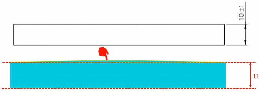
GD&T Rule 1, also known as the envelope principle or Taylor principle, states that the form of a regular feature of size is dictated by its limit sizes. The surface of a regular feature cannot extend beyond the envelope created by its maximum material condition (MMC) and least material condition (LMC). This rule is applied by default in drawings conforming to the ASME Y14.5 standard. If a plate has a thickness of 10 mm ± 1 mm, both the top and bottom surfaces must remain within an envelope defined by 11 mm and 9 mm.
GD&T Rule 1 Envelope Principle
When a feature is manufactured at its MMC, such as a plate exactly 11 mm thick throughout, the MMC boundary is completely filled with material. In this scenario, if the plate is bent even slightly, the surface would extend beyond the MMC boundary, which is not permitted. As a result, at MMC, the plate must be perfectly flat. Industries often refer to this as “perfect form at MMC”: perfect flatness, straightness, circularity, and cylindricity are required at MMC, while form deviations are allowed only when the part is not at MMC.
GD&T Rule 1 Applications
This principle helps ensure proper assembly of individual features with other components. For example, a shaft that needs to fit in a hole with a clearance fit (such as a 7 G6 fit) depends on this rule. If the shaft’s nominal size is 20 mm, with a tolerance of -0.01 mm to -0.02 mm, and the hole is 20 mm with a tolerance of 0 to 0.02 mm, the shaft diameter can range from 19.98 mm to 19.99 mm, and the hole diameter from 20 mm to 20.02 mm. The most restrictive assembly occurs when the shaft is at its largest and the hole at its smallest, leaving only a 0.01 mm clearance. In such a case, both the shaft and hole must be perfectly straight and perfectly cylindrical to maintain the fit. Thanks to Rule 1, no additional geometric form controls need to be specified for these features at MMC.
GD&T Rule 1 Pros & Cons
Advantages: Rule 1 relieves designers from the need to specify additional geometric tolerances for fit at worst-case assembly conditions. It guarantees that form deviations are controlled automatically at MMC, helping achieve precise assemblies.
Limitations: Rule 1 applies only to individual regular features of size, not to irregular features or the entire part as a whole. It does not control orientation variation within the limit size (such as the angle between features), nor does it apply to non-rigid parts like rubber components or belts, or to stock/raw material sizes. Rule 1 also does not guarantee that all geometric relationships (like perpendicularity) are maintained.
GD&T Rule 1 Solution & Examples
Consider a block with thickness 10 mm ± 1 mm and width 20 mm ± 1 mm. Rule 1 applies to both thickness and width as individual features, but not to the block as a whole. If both sides are at MMC, their flatness must be perfect, but the angles at the corners are not controlled by Rule 1. Additional controls, such as perpendicularity, are required for such geometric relationships.
If a plate’s thickness is at MMC (11 mm), it must be perfectly flat, with no bending allowed. Any deviation in form at MMC means the part will not meet the requirements and should be rejected.
What is GD&T Rule 2?
GD&T Rule 2 establishes that “regardless of feature size” (RFS) applies to individual tolerances when no modifying symbol (such as MMC or LMC) is present in the feature control frame. This rule defines the default condition for geometric tolerances, making them independent of feature size unless specifically stated otherwise.
GD&T Rule 2 Envelope Principle
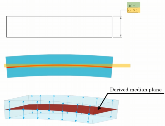
The RFS condition means that geometric controls, such as flatness, position, straightness, perpendicularity, circularity, and runout, are not directly linked to the size variation of the feature. For instance, if a plate’s thickness is 10 mm ± 0.5 mm and a flatness tolerance is applied to the top surface, the flatness deviation remains 0.5 mm regardless of the actual thickness (9 mm, 10 mm, or 10.5 mm).
GD&T Rule 2 Applications
Rule 2 is used when geometric controls need to be independent of the feature’s size. A flatness or straightness tolerance applied to a surface or the median plane of a feature will remain constant across the full range of allowable sizes, unless MMC or LMC modifiers are used.
GD&T Rule 2 Pros & Cons
Advantages: Rule 2 provides flexibility by allowing geometric tolerances to be set independently of size, which can simplify inspection and manufacturing for many features.
Limitations: At times, this independence can result in situations where the actual envelope of a feature is larger than expected, especially when form deviation and size deviation are both at their maximum. Additionally, Rule 2 may not be suitable when a perfect fit at worst-case assembly is needed.
GD&T Rule 2 Solution & Examples
If a plate with thickness 10 mm ± 1 mm has a 0.5 mm flatness tolerance applied to the thickness dimension, and no MMC or LMC modifier is present, the flatness and size tolerances are independent. The maximum envelope occurs when the plate is at 11 mm and also exhibits 0.5 mm flatness deviation, resulting in an envelope of 11.5 mm.
For a shaft of diameter 10 ± 1 mm with a straightness tolerance of 0.5 mm applied to the size dimension, the shaft can be as large as 11 mm and still have a straightness deviation up to 0.5 mm. This results in an envelope boundary of 11.5 mm.
GD&T Rule 1 & Rule 2 Differences & Relations
| Aspect | Rule 1 | Rule 2 |
|---|---|---|
| Envelope Principle | Form is controlled by the limit size; perfect at MMC | Geometric controls are independent of size unless modified |
| Default Condition | Applies to individual regular features of size | Applies when no modifying symbol is present |
| Form Control at MMC | Perfect (no deviation allowed at MMC) | Form deviation may exist at MMC if no modifier is used |
| Applications | Ensures assembly at worst-case condition | Provides independence for geometric tolerances |
| Overriding | Can be overridden by Rule 2 or with independency symbol | Overrides Rule 1 when applied to the median plane or with no modifier |
In some situations, Rule 1 does not apply and is overridden by Rule 2, while in other cases, Rule 2 is superseded by Rule 1. For example, applying a flatness tolerance to the size dimension of a planar feature, or a straightness tolerance to the size of a cylindrical feature, places Rule 2 in precedence. The independence symbol can also override Rule 1.
Both rules are applied by default in most situations, but understanding their scope and limitations ensures that the intended function and manufacturability of the part are consistently achieved.