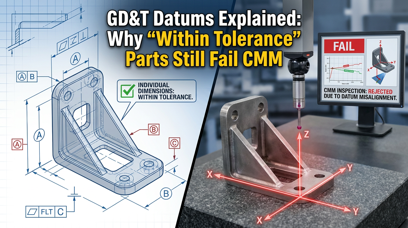
In precision machining, there’s a particular kind of failure that’s both confusing and dangerous: The part is finished. The surfaces look clean. Every dimension appears to be within tolerance. The machining report shows the program ran successfully. Then the part lands on the CMM, and it’s rejected immediately.
The operator is confused. The programmer is frustrated. The manager is upset. Where exactly did things go wrong?
The answer often has nothing to do with the dimensions themselves. It has everything to do with datum logic. To truly understand why this happens and why it occurs so frequently, we need to take a step back and examine what datums actually are, how they function, and why they form the foundation of every engineering drawing.
The Case: How a “Reasonable” Global Offset Destroyed a Part
A programmer reviewed a drawing and saw negative tolerances on both outer edges. Following a fairly common instinct – to compensate for stock and ensure clean assembly fits – he applied a global offset in the program, shifting the entire profile inward.
From a machining standpoint, this looked perfectly logical. Some would even call it a smart move.
But he overlooked one critical detail: a keyhole feature on that part was dimensioned from the LEFT DATUM (Datum A).
That single fact changes everything:
- The outer profile was allowed to float (within its own tolerance)
- But the hole position had to be strictly controlled relative to Datum A
When the global offset was applied, the hole moved along with the outer profile. The result?
✔ Overall dimensions looked acceptable
✔ The part visually looked correct
✔ The machining program completed without issues
✘ But the hole had drifted relative to Datum A
✘ CMM caught it instantly
Why Is This One of the Most Dangerous Mistakes in Precision Machining?
Because it has every characteristic of a “hidden defect”:
The part looks good. The dimensions look close to nominal. The machining process shows no anomalies. But the datum logic is already broken, and that kind of failure is invisible to the eye, invisible to calipers, and invisible even to program simulation.
The truth only emerges when the part enters the CMM’s measurement coordinate system, where Datum A, B, and C are constructed exactly as the drawing specifies. Only then does the failure reveal itself.
This is why understanding datum theory is not optional knowledge, it is the very framework that determines whether a part passes or fails.
What Exactly Is a Datum in GD&T? Going Back to the Definition
Many machinists treat datums as if they were simply “edges to measure from.” That casual interpretation is precisely what causes failures like the one above.
In ASME Y14.5 terminology, a datum is a theoretically perfect point, line, or plane. It establishes the origin from which the location and geometric characteristics of features are derived.
It’s important to distinguish three terms that are often used interchangeably but mean very different things:
- Datum – The theoretically perfect geometric reference (a perfect point, line, or plane that exists only in concept).
- Datum Feature – The actual physical surface on the part that is identified as the reference (a real surface that is never perfectly flat or perfectly cylindrical).
- Datum Feature Simulator – The physical inspection equipment (surface plate, mandrel, gauge pin, vise jaws, CMM probe) used to approximate the perfect datum.
When a CMM inspects a part, it doesn’t measure from “the bottom edge.” It constructs a perfect mathematical plane from the high points of the actual surface, and uses that as the reference. If the part was machined assuming the datum was somewhere else, the discrepancy shows up immediately.
GD&T Datum Reference Frame: The Skeleton of Every Drawing
Datums never exist in isolation. They live inside a structure called the Datum Reference Frame (DRF) -three mutually perpendicular planes (XY, YZ, ZX) that together form a Cartesian coordinate system specific to the part.
The main function of the datum reference frame is to specify the foundation for inspection. It is the common coordinate system shared by every tolerance zone on the drawing.
Any feature that is dimensioned with basic dimensions and a feature control frame is being controlled within this frame. Move the frame, and you move every controlled feature with it. This is exactly why the global offset in our case study was so destructive, it didn’t just shift the outer profile, it implicitly shifted the relationship between the hole and Datum A.
Six Degrees of Freedom: How a Part Gets Locked Down
To understand why datum order matters, you have to understand the concept of degrees of freedom.
Every part in 3D space has six degrees of freedom: three translational (movement along X, Y, and Z) and three rotational (rotation about X, Y, and Z). Inspection means progressively eliminating these degrees of freedom in a controlled, repeatable way.
The datum reference frame establishes the order in which the part is constrained:
- Primary Datum (3 points of contact, not in a straight line): The primary datum feature sits flat against the first plane of the DRF. This eliminates three degrees of freedom – one translational and two rotational.
- Secondary Datum (2 points of contact): The part is then pushed against the second plane. This eliminates two more degrees of freedom – one translational and one rotational.
- Tertiary Datum (1 point of contact): Finally, the part is slid until it contacts the third plane. This eliminates the last translational degree of freedom.
This is the famous 3-2-1 fixturing principle that underpins every CMM setup, every fixture design, and every inspection routine.
The order matters. A-B-C is not the same as B-A-C. If your machining setup uses a different reference order than the drawing specifies, the part may pass on your fixture but fail on the inspector’s plate.
How Datums Are Selected and Why That Choice Is Never Arbitrary
When a designer chooses a datum, they aren’t picking a convenient surface. They’re communicating functional intent. Good datum selection follows four key principles:
- Functional Surfaces – Datums should be chosen from surfaces that perform a function in the assembly. The surface that mates with another part, carries load, or aligns with a mechanism is almost always the right datum.
- Mating Surfaces – Surfaces that physically contact other parts at assembly are critical. Dimensioning from these surfaces ensures that the manufactured part will assemble correctly.
- Readily Accessible Surfaces – A datum that cannot be reached easily by inspection equipment is a poor datum. If a CMM probe or a height gauge can’t access it cleanly, repeatable measurement becomes impossible.
- Surfaces of Sufficient Size – Small datum surfaces amplify measurement error. A datum needs enough area to support multiple, repeatable contact points.
When you understand these criteria, you start to see datums not as “where to measure from” but as a deliberate engineering decision encoding how the part is meant to function.
A Drawing Is Not a Collection of Dimensions – It’s a Functional Relationship
This is a fundamental concept that too many shops fail to internalize:
An engineering drawing is not a list of “numbers you must hit.” It is a network of functional relationships built from datums, features, and tolerances.
Once a feature is controlled by a datum structure, you cannot redistribute its tolerance freely just because it would be more convenient for machining.
Datum always overrides convenience – This sentence deserves to be posted on the wall of every CNC programming station.
Where Datum Symbols Sit on the Drawing and Why It Matters
One subtle but critical area where misinterpretation creeps in is the placement of the datum feature symbol itself. The same letter, in two slightly different positions on a drawing, can mean two completely different things.
- Attached directly to the surface (or to an extension line, off the dimension line): The datum is the surface itself. Inspection means laying that physical surface flat against a reference plane.
- Attached in line with a dimension: The datum is no longer the surface; it is the center plane running through the feature. Inspection requires a centering vise or a derived median plane construction.
This is why experienced designers often flip the datum feature symbol upside-down when applying it to an extension line, to guarantee it can never be mistaken for a center-plane datum, even if the drawing is later edited and elements shift around.
The same logic applies to feature control frames:
- Outside the feature control frame, on an extension line, typically indicates a surface datum.
- Attached to the side of the feature control frame, this indicates that the toleranced feature itself is also a datum (commonly a feature of size).
- Pre-1994 convention: A datum symbol on a feature control frame implied a feature of size. Post-2009 standards allow it on any feature, which means readers must look more carefully.
If your team interprets these symbols casually, the entire chain of inspection logic collapses before the first cut is even programmed.
Material Condition Modifiers: Bonus Tolerance vs. Datum Shift
Another layer that is frequently misunderstood is the use of material condition modifiers (MMC, LMC, RFS) attached to datum references.
When you see an MMC symbol next to a tolerance value in the feature control frame, it grants bonus tolerance; the toleranced feature gets additional tolerance as it departs from MMC.
When you see an MMC (or MMB) symbol next to a datum reference, it does something completely different. It grants datum shift; the part is allowed to move slightly within its inspection fixture, because the fixture is built to the virtual condition of the datum feature, not its actual size.
This distinction has enormous practical implications:
- A datum at RFS (Regardless of Feature Size) typically requires expensive centering vises or precision collapsing jaws.
- A datum at MMB (Maximum Material Boundary) can be inspected with fixed gauging — a simple pin or boss made to virtual condition. This is what allows automated robotic inspection and go/no-go gauges to work efficiently.
When a programmer ignores these modifiers, they might either over-restrict the part (making it harder to machine and inspect than necessary) or under-restrict it (allowing a non-functional part to pass). Either way, it’s a costly mistake.
Datum Targets: When Surfaces Aren’t Reliable Enough
Not every part has clean, flat surfaces suitable for full-contact datum referencing. Castings, forgings, sheet metal stampings, and plastic injection moldings often have draft angles, parting lines, surface texture, and dimensional variation that make full-surface contact unrepeatable.
For these parts, designers use datum targets: specific points, lines, or areas of contact rather than entire surfaces.
The datum target symbol is a circle divided in half. The lower half identifies the datum letter and target number (e.g., A1, A2, A3). The upper half indicates the size and shape of the target if applicable.
A typical 3-2-1 datum target setup might look like:
- Three target points establishing the primary datum plane (A1, A2, A3).
- Two target points or lines establishing the secondary datum (B1, B2).
- One target point establishing the tertiary datum (C1).
The choice of target type is also functional:
- Pad targets are used on heavy parts where point contacts would wear or deform.
- Point targets work well for lightweight parts and CMM inspection, where a single repeatable point of contact gives the best measurement consistency.
- Line targets are often used on curved geometry, because a point on a curve can shift along the tangent, while a line stabilizes the contact.
If a casting comes in with a datum target scheme and the machine shop fixtures it on its general surfaces instead, the entire reference frame is misconstructed before the first measurement is even taken.
Multiple Datum Reference Frames: A Practical Necessity, Not a Loophole
For long parts, complex assemblies, or parts where different features serve unrelated functions, designers sometimes specify multiple datum reference frames.
For example, imagine a five-foot bar with one hole at each end. Forcing both holes to be measured from the same A-B-C frame at one corner of the bar would introduce massive accumulated tolerance and require inspection equipment capable of spanning the entire length accurately. Instead, the designer might establish a secondary datum (D) on the opposite end, controlled by profile back to A-B-C, and locate the second hole from A-B-D.
This approach has real advantages: easier inspection setup, more practical tolerance allocation, and better alignment with each feature’s actual function. But it also requires the machinist to understand which frame applies to which feature, and to never assume that “datums for one feature” mean “datums for the whole part.”
When Teams Start Reading Drawings Emotionally Instead of Systematically
We see this happen far more often than people realize, especially when:
- GD&T understanding is weak — people only look at ± values and ignore the feature control frames
- Datum strategy is dismissed — Datums A, B, and C are reduced to “reference lines”
- Shops rely on visual judgment instead of systematic inspection logic
- Material condition modifiers are ignored, leading to mismatched fixturing and inspection methods
- Datum targets are treated as suggestions rather than mandatory contact specifications
Once a drawing is interpreted emotionally rather than systematically, the entire process begins to collapse:
Programming becomes guesswork. Inspection becomes debate. Assembly becomes risk.
This isn’t a technical issue, it’s an engineering culture issue.
A Useful Analogy: Thread Standards
If a drawing specifies “M6” without explicitly noting a left-hand thread, ISO convention defaults to a right-hand thread.
You cannot machine a left-hand thread and then argue: “The drawing didn’t forbid it.”
Engineering drawings already contain a great deal of implied logic, established conventions that don’t need to be restated on every line.
GD&T datum logic works exactly the same way. There’s no need for a note next to every feature saying “please respect Datum A,” because that’s the default contract of engineering language.
Industry Reality: Why This Problem Is So Widespread
A senior mechanical design engineer once shared a strikingly honest reflection:
“I’ve worked in mechanical design for many years, and I’ve met very few people who truly understand GD&T per ASME Y14.5. Most engineers and designers ignore GD&T entirely and rely solely on the title block ± tolerances. Management doesn’t enforce proper training or promote correct usage. On the contrary, my boss has even told me to avoid using GD&T because he believes it complicates the drawing and causes manufacturers to raise their bids. This is the sad reality.”
Another engineer added an equally sharp observation:
“When datum relationships are not respected, dimensional compliance alone becomes misleading. The part may pass size checks but fail functional intent. Many machining environments optimize for local dimensional conformance instead of system-level geometric control defined by the datum scheme. The datum structure is the functional backbone of the drawing.”
Together, these voices reveal a deep industrial pain point:
Many companies treat GD&T as a cost rather than as a quality assurance tool. But the truth is, GD&T isn’t what’s expensive. What’s expensive is the consequence of not using it properly:
- Assembly failures
- Rework and scrap
- Customer complaints
- Field returns and recalls
- Lost contracts due to repeated CMM rejections
What Does a Truly Capable CNC Supplier Look At?
The essence of precision machining was never simply “hit the dimensions.”
A truly professional supplier asks deeper questions the moment a drawing arrives:
- Datum Intent – Why did the designer choose these specific surfaces as datums? What does that say about how the part assembles, how it’s loaded, how it functions? Is there a primary mating surface that drives the entire reference scheme?
- Datum Feature Type – Are the datums planar surfaces, features of size, threaded features, or pattern-based? Each requires a different fixturing strategy.
- Material Condition Modifiers – Do the datums apply at RFS, MMB, or LMB? Does this allow simpler fixed gauging, or does it require a precision centering setup?
- Tolerance Stack-Up – Once a chain of features stacks together, does the functional dimension still hold?
- Inspection Strategy – How should this part be measured? CMM? Optical comparator? Custom gauge? Datum target fixture?
- Manufacturability Logic (DFM) – Does the datum structure align with how the part will be fixtured? Is a design discussion needed?
A truly capable supplier doesn’t just machine parts. They understand how the part is supposed to function.
Practical Takeaways for Programmers, Inspectors, and Engineers
Before applying any global offset, operator override, or “smart compensation” to a CNC program, ask the following:
- Which features are controlled by which datums? Map the feature control frames to the datum reference frame before touching the program.
- Will my offset move features that must remain fixed relative to a datum? If yes, the offset must be local, not global.
- What is the order of datum precedence (A, B, C)? Does my fixture replicate that order?
- Are there material condition modifiers that change how the part should be fixtured? Is fixed gauging acceptable, or does the part need precision centering?
- Does my inspection strategy match the drawing’s datum structure? A part inspected against the wrong frame is not really inspected at all.
These five questions, asked consistently before machining begins, eliminate the vast majority of CMM rejections caused by datum misinterpretation.
“Within tolerance” sounds rigorous, but it’s actually one of the most dangerous phrases in manufacturing. Because it implies a false assumption: that all dimensional tolerances are equal and freely interchangeable. In the world of GD&T, that’s simply not true. Datum-controlled features carry higher priority. They are not “references”, they are the skeleton of the part. Once that skeleton is distorted, even if every other muscle “looks” correct, the part has already lost its functional integrity.
Precision machining, at its core, is a careful dialogue between geometric logic, engineering language, and functional intent.
Reading a drawing correctly starts with reading the datums correctly. Everything else — every dimension, every tolerance, every inspection result, is built on that foundation.