Geometric Dimensioning and Tolerancing (GD&T) is a detailed system used in engineering and manufacturing to define the allowable variation in part geometry. As part designs become more intricate, advanced GD&T techniques are needed for proper control. Among these, composite position tolerancing and the use of two single segments often arise as topics of focus. Understanding how these two approaches function, and how they differ, can help ensure proper fit and function of assembled parts.
What is Composite Position Tolerance in GD&T?
Composite position tolerancing involves using a single position symbol applied across two feature control frames stacked in a single callout. The upper segment acts just like a standard position tolerance, controlling the location of features, such as holes, relative to the datums. For example, this might require positioning features within a specific tolerance (e.g., 0.6 mm) relative to designated datums.
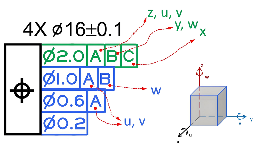
The lower segment serves as a refinement of the upper, focusing on the relationship between features within a pattern. It controls the orientation (rotation) of the features relative to the datum reference frame, but does not further constrain their location to the datums. Instead, it tightens the location between the features themselves. This means that while the upper segment addresses both translation and rotation, the lower segment constrains only rotation, helping maintain parallelism or perpendicularity relative to the selected datums, but not their absolute position.
A practical example involves a group of holes with two tolerances: the upper one ensures the holes are within a certain tolerance to the datums, while the lower one makes sure the spacing and orientation among the holes is controlled more tightly. The upper segment is often called the pattern locating tolerance zone framework, and the lower segment is called the feature relating tolerance zone framework.
What is Multiple Single Segment Tolerance in GD&T?
Two single segments refer to using two separate position callouts, each with its own feature control frame. In this approach, the upper segment specifies location of the features relative to the datums, and the lower segment applies a tighter positional tolerance, again relative to the datums.
With two single segments, both segments behave like standard position tolerances to the datums. Each feature control frame constrains as many degrees of freedom as possible—both translation and rotation, relative to the specified datums. There is no refinement of relationship between the features as a group; instead, both segments independently control the entire pattern’s position and orientation relative to the datums.
GD&T Composite Position Tolerance vs Two Single Segment Tolerance: What are the Differences?
The difference between composite position and two single segments lies in how they control feature patterns and their relationship to datums. These differences between them affect how part features are inspected and assembled, and choosing the right method depends on the functional needs of the design. Below we’ve sorted out the main differences between them:
1. Control of Feature Location Relative to Datums
- Composite Position:
The upper segment manages the location of the feature pattern as a whole relative to the datums. The lower segment does not further constrain the location of the pattern to the datums; instead, it refines how the features are grouped together. - Two Single Segments:
Both segments control the location of the features relative to the datums. Each frame applies its tolerance directly to the datums, without any separation between pattern location and internal feature relationship.
2. Internal Relationship Between Features
- Composite Position:
The lower segment specifically controls the internal spacing and orientation between the features within the pattern. It tightens how the features relate to each other, allowing the pattern to shift as a unit within the larger tolerance zone. - Two Single Segments:
There is no refinement of the internal pattern. Both segments apply their tolerances to the features relative to the datums, treating each feature independently in both cases.
3. Degrees of Freedom Constrained
- Composite Position:
The upper segment constrains both translation and rotation of the pattern to the datums. The lower segment only constrains the orientation (rotation) of the features to the primary datum, not their position. - Two Single Segments:
Each segment constrains as many degrees of freedom as possible—both translation and rotation—relative to the datums in every case.
4. Application in Manufacturing
- Composite Position:
Useful when the functional requirement is more about the group of features being precise to each other than to their absolute location on the part. It allows for easier manufacturing since the pattern can float within the part as long as the internal relationship is maintained. - Two Single Segments:
Required when both the absolute position of the pattern and the individual features need to be tightly controlled to the datums, with no relaxation between pattern and datum relationship.
5. Feature Control Frame Structure
- Composite Position:
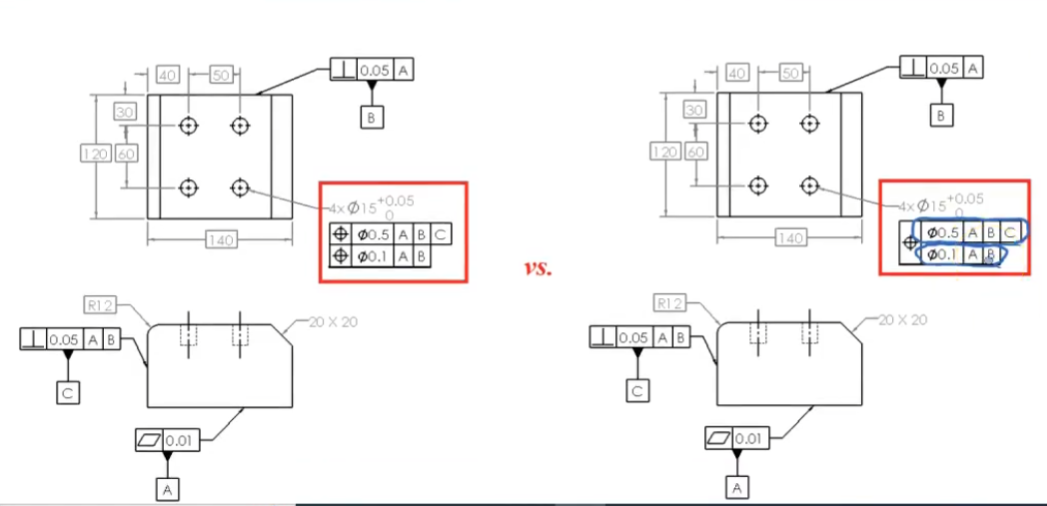
A single position symbol is used, with two stacked frames—one for overall pattern location, one for internal refinement. - Two Single Segments:
Two separate position callouts are used, each with its own complete feature control frame, both applied to the datums.